
Position
The guided first support aligns and advances the blade into the machining area.
HBBA / ROTOR BLADE ROOT MACHINING
Your diameter. Your connection design. Your production. We design and manufacture the HBBA around your application – for onshore and offshore rotor blades.
Discuss your HBBADownload brochures ↓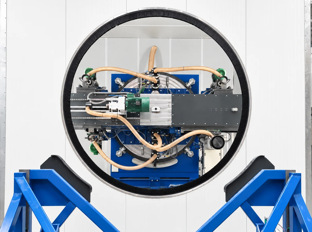
01 / ONE INTEGRATED PROCESS
For composite blade roots after bonding and demoulding. The HBBA brings blade handling and machining together in one coordinated process.
The guided first support aligns and advances the blade into the machining area.
A PCD saw trims the excess laminate from the blade root.
The milling unit finishes the flange face to the required plane and final blade length.
Axial and radial units work in parallel. Programmable cycles follow the specified hole pattern.
02 / CONNECTION DESIGN
Axial threaded studs engage cross-bolts seated in radial holes. The HBBA combines face machining with the required drilling operations.
An insert connection also requires a precisely machined end face. The HBBA can be configured as a milling-only machine with two milling units.
HBBA / CONFIGURATION
From smaller roots to large rotor blades: the working range, supports and machining functions are engineered for your geometry. An example diameter in the brochure is not an upper machine limit.
We review your blade drawing, connection design and production targets with you. Together, these define the machine configuration, installation plan and site requirements.
PLANNING EXAMPLE / OFFSHORE
Reference figures from an example offshore installation, not universal utility or construction specifications. Allow extra space for the complete blade, further supports, transport and maintenance. Foundations, utilities and protection follow the approved machine documentation.
Development and manufacturing in Lemwerder, coordinated on-site commissioning and after-sales support for the machine in use.
Heinicke has supplied cross-bolts and threaded studs in series production for wind turbine blades. Component selection, dimensions, materials and finishes follow the approved drawing and blade specification.
Internally threaded inserts for direct bonding into the blade root.
Transverse internal threads engage the axial threaded studs.
Connect through the axial holes into the cross-bolts.
Retouched reference images from the HBBA brochure.
Process, configuration, equipment options and site planning guidance in PDF format.
Both language editions contain 12 pages, including connection designs and equipment options.
HBBA / HEINICKE
Share your root geometry, connection design and production targets. Together, we will configure your HBBA.
Discuss your HBBA